![]() Phone: 605-554-1911 | Email : [email protected]
Phone: 605-554-1911 | Email : [email protected]
Rifle Sighting Systems - Part 2: Angular Mil
Mar 21, 2011Written By - Greg Dykstra
© Copyright 2009 - Present - Primal Rights Inc
ALL RIGHTS RESERVED
No part of this website or any of its content may be reproduced, distributed, or transmitted in any form or by any means without the express prior written permission of Primal Rights, Inc
Having read the first part in the Rifle Sighting Systems series, you know that shooting is an angular sport. In the earlier article you learned about the MOA and IPHY units of angular measurement. Today we will go into detail about another angular unit of measure call the Angular Mil. This system has been widely used by NATO military forces since around the time of World War I as a means to sight field artillery. By the end of this article you will learn how to use a mil-based rifle scope and deploy it effectively in the field.
The Mil system was originally adopted in the current NATO form by the French as an alternate to decigrades as the primary unit of measure to sight field artillery shortly after World War I. It was shortly after that time that the United States adopted it for the same purpose. The push for a standardized unit of measure among NATO forces lead the charge during this time period and is the primary reason for adoption of the metric system by the United States military and allied forces. With this being the case, it is often thought that the angular mil is a metric measurement. This is a false but understandable assumption considering the consequential linear associations, as you will see in a moment. While it may be insignificant, it holds true that the mil system is not metric, nor imperial, but an angular unit of measure just as MOA and IPHY.
One mil is 1/6400th of a circle. Just as with the MOA system, which is broken down from 360 degrees of a circle, the mil system is based on 6400 mils in a complete circle. The actual number of mils in a circle can be somewhat confusing due to the fact that different countries claim different numbers. NATO countries recognize that there are 6400 mils in a circle. The actual trigonometric measurement calls for 6283 mils in a circle. Non-NATO countries have even different interpretations. It is up to you which interpretation you want to adopt, but personally, I will side with the U.S. military! Thus, for our purposes we will contend that there are 6400 mils in a circle.
The linear distance covered by one mil is identical in its behavior to MOA and IPHY in that it increases as the distance to the target increases. In the illustration below, you can see that one mil covers 3.6" at 100yds and 7.2" at 200yds. This behavior is true of all angular units of measure.

As you can see, one mil covers more than three times the linear distance than one MOA does. This results in much smaller mil numbers to gain an equal adjustment that a larger MOA number provides. For instance, we discussed that for a typical short-barreled 308win to reach 1000yds that approximately 42 MOA of adjustment would be required when using 175gr bullets. To reach that same distance with an identical trajectory would take 12.2 mils of adjustment. These numbers are simply estimates to show the differences between the two units. Real world drop will be different for every load and rifle combination, so proper application of a ballistic computer should be employed to get your exact drop. We will cover ballistic computers in a future article on Primal Rights.
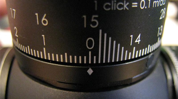
Optics manufacturers seem to be much more standardized when it comes to the mil system when compared to MOA. Typically, most mil-based rifle scopes are set up with 1/10th click turrets. This means for every click of the turret you will adjust for 0.1 or one tenth of a mil. This translates to a linear difference of 0.36" at 100yds or about 1/3 of an inch. This is slightly more coarse than the 0.25" typical adjustment of MOA turrets and vastly more coarse than 1/8 MOA clicks. That being said, I have not encountered a single situation in a match, hunting, pounding steel, or target shooting where the 0.1 mil clicks were not precise enough to make the adjustment required to hit the target. One click at 1000yds translates into a 3.6" linear adjustment. That is pretty small.
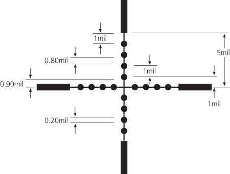
The reticles offered by most companies are also somewhat standardized. The various different mil reticles carry different names for the type of reticle they represent, as well as specific names given to them by their manufacturers. The original mil-dot reticle is as you see below. The measurements of the reticle are what is referred to as "sub-tensions" which is simply a description of how the reticle is laid out. You can see that the dots cover a 0.2 mil area, and there is a 0.8 mil space between each dot. This style of reticle is referred to as a standard mil-dot.
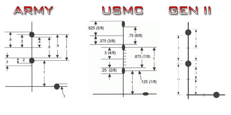
Here you see three basic styles of mil reticle that are used, and their subtension mapping. Typically the reticles are able to be broken down into 1/10th mil increments easily enough. Newer reticles such as the Gen II style have a hash mark at the 0.5 mil mark. This gives you another aiming point and adds a visual reference to make it easier when breaking the reticle into tenths in your head. There are many different styles of mil reticles available today, these are just three samples in common usage.
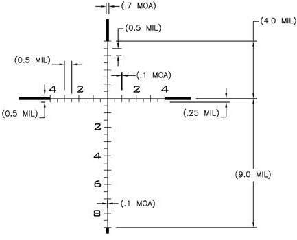
Another style of reticle is the mil-dash. As you might imagine, it is spaced similarly but uses varying sizes of dash marks rather than dots. The GAP reticle is an example of a mil-dash style.
As manufacturing techniques evolved, there became better and easier ways to produce reticles. The glass etched reticles offered detail and freedom of design that were unattainable with the "wire" reticles of the past. This has spawned an entire generation of reticle design. Below you see the Gen II XR offered by Premier Reticles, and its one of my personal favorites. This takes the standard gen 2 design and adds numbered holds as well as a "christmas tree."
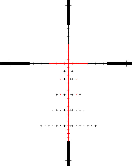
Some say these types of reticles are too "busy" and distract the shooter. While this can be true in some instances, when an enhanced mil reticle like this is done right, it simply gives you more options as a shooter. The christmas tree gives you an ability to apply precise wind and elevation holds without having to dial the turrets. This can come in very handy when you are under time pressure and have to make accurate shots on targets at various distances. It also gives you the ability to make very precise follow-up shots. Because the christmas tree can be used as a "grid" of sorts, you can call the correction down to the tenth of a mil if you see the bullet impact clearly enough.
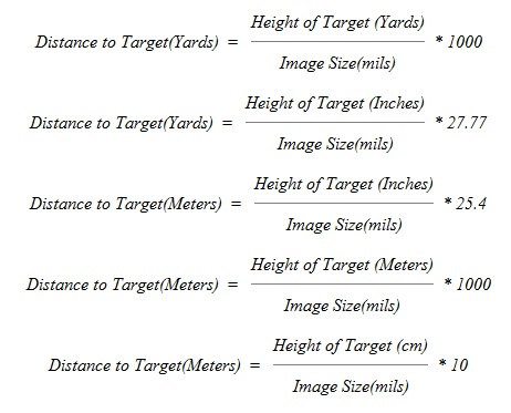
Ranging with the mil system, just as with the other systems, is dependent on how accurately you can read the reticle. For shots inside of 1000yds, it is generally accepted that if you can read the correct target size in mils down to 1/10th of a mil, you should be able to get close enough to the actual range to ensure a hit. Having a flat trajectory and a high ballistic coefficient bullet will increase your chances. Here are the various formula's that you can use to estimate range using a mil reticle:
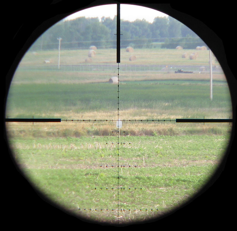
In the image above I am using a Premier 5-25x56 mil/mil/ffp scope with the Gen II XR reticle. The target is a standard IPSC sized AR500 steel silhouette. I know the size of the target is 30" from the top of the head to the bottom. In order to find the distance, I must take a reading to see how tall it is in mils. This is something that gets easier with practice, and can be made more difficult by shooting in heavy mirage. Typically when ranging, you will want to level the crosshairs at either the top or bottom of the target on either the left or right side. This will allow you to bracket it using the reticles subention and make the reading easier to achieve. It is somewhat difficult to aim a rifle while aiming a camera through the scope, so we'll compromise a bit here. There is approximately 1/10th of a mil above the crosshair, and about 2/10ths beneath the 0.5 mil mark. That gives us a reading of 0.8 mils. In accordance with the above formula, we would take 30" divided by 0.8 which gives us 37.5. We then multiply 37.5 by 27.77 which equals 1041.675. It is safe to drop everything after the decimal as half a yard is pretty insignificant. So, based on a target size of 30" and a mil reading of 0.8mils the range to target is 1041yds.
What if you read the reticle wrong? What if instead of 0.8 mils, it was actually 0.7 mils. Well, that would mean the target is at 1190yds rather than 1041yds! This illustrates the importance of making accurate readings, as well as clearly shows the limitations of the mil ranging system. You would have to be shooting a very fast rifle with a high BC bullet to be off by just one tenth of a mil and still impact your target at those ranges. Don't let this turn you off to mil ranging, as it is a very effective method to know in the case that your beloved laser range finder (LRF) fails to function.
There are many effective shortcuts to mil ranging that do not involve running the calculations manually. The mil-dot master is one of these methods. It is a slide-rule type device that will allow you to easily input your target size, mil reading, and be given your distance to target. My preferred method is to use a target size to mil relation chart in my databook. When giving target size in inches, obviously there can only be one solution for each mil reading in tenths to each added inch of target size. Thus, you get the same result whether you do the math manually or simply glance at this chart. Here is one page of the front/back tenth mil relation page in my databooks:
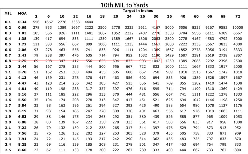
As you can see, you simply find the size of target in inches on the top row, then move down the left colum in 0.1 mil increments until you match your mil reading. Where the two meet equals your distance to target. I have highlighted the solution we did for the target above as an example.
In order for your reticle readings to be correct when using a variable power scope, you must be on the correct power if using a SFP reticle. If using a FFP reticle, you do not have to worry about the power setting, as the reticle is calibrated and subtends correctly at all powers. In the next part of this series on rifle sighting systems we will discuss SFP and FFP in detail.

